When FRONT of HOUSE’s intrepid editor George Petersen suggested I write on the topic of loudspeaker horns, I was immediately interested, and a little overwhelmed. Improving horn behavior is a topic of personal interest. Discussing the operation of horns is a huge subject, and the underlying math that describes how horns operate is complex and poorly understood — even by horn designers. Despite these challenges, horns are too interesting a topic to ignore.
Given that premise, let’s discuss some concepts about how horns operate and how sound waves travel through them. First we will introduce the acoustic and directional functions of horns. Next we will discuss how sound moves through a horn from the driver into the open air.
Horn Core Functions
All horns and waveguides perform one specific task, namely the transition of sound from one end of a tube with a given cross-sectional area to the other end of that tube with a different cross-sectional area. More specifically, horns are designed in such a way that a high “pressure” near the sound source (e.g. compression driver) is converted to a high “volume velocity” near the horn’s exit, also know as the horn “mouth.”
Pressure, which is defined as [Force ÷ Area], is a concept many are familiar with. Not so with volume velocity. Volume velocity is defined as [Particle Velocity × Area]. It can be thought of as the quantity of air particles that are being swept back and forth at a given speed in a given direction as the sound wave passes by. It is important to note that this velocity is not the speed of sound, but rather the speed of the displacement of the air particles from their rest position as the sound wave moves past. The wave travels at the speed of sound, but the air particles do not. The particle velocity is typically much lower than the speed of sound, and there is no net displacement of the air particles.
A device like a compression driver is able to exert a high force, and therefore a high pressure, on a comparatively small area of air molecules. One would like to distribute that pressurization over a larger region of air molecules moving in concert with each other at a higher particle velocity. A horn’s expanding length accomplishes this transition in a controlled fashion.
The intensity of sound is defined as [Pressure × Particle Velocity] and has units of [Energy ÷ Area]. Thus, for a sound wave to carry energy, it must have appreciable values for both pressure and velocity. A compression driver without a horn can exert pressure, but without the horn’s expansion, this pressure does not result in increased particle velocity, and little acoustic energy is transmitted. Adding the horn’s expanding transition enables pressure from the driver to result in higher velocity, and the transmission of more acoustic energy.
In addition to aiding transfer of acoustic energy, horns in modern professional loudspeakers provide control over the directional behavior of where sound travels. We tend to think of the directional control as a horn’s primary acoustic purpose, but directional control is a relatively new realm of function for loudspeaker horns. Early horns were primarily concerned with optimum acoustic loading of the compression driver. As compression driver performance has improved, directional control has superseded acoustic “loading” as the most critical function performed by loudspeaker horns.
Sound Moving in Horns
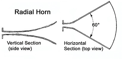
The horns we use in pro sound applications have three universal physical characteristics. First, these horns have a “throat,” or narrow end where a loudspeaker is mounted. Second, horns have a mouth where sound exits into the air. Finally, they have a “flare” which transitions between the throat and the mouth. Sound from the loudspeaker enters the horn at the throat and then exits at the mouth after expanding through the flare. These three features define the performance and limitations of a horn. Real horns are inherently finite devices. They cannot be arbitrarily large, arbitrarily deep, and must mate with real-world loudspeaker drivers.
The Throat
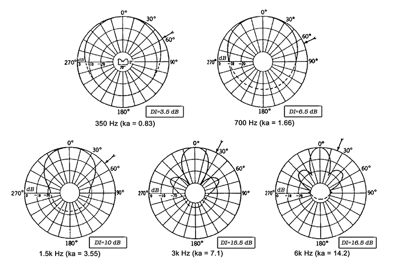
The confines placed on performance start at the horn throat. For most of the frequency range, the wavelength of sound has larger dimensions than the throat, but at the highest frequencies, this is no longer true. Once the wavelength becomes comparable to the throat diameter, there is opportunity for sound to move through the horn in such a way that its directional behavior is no longer well controlled. This commonly causes the directional response of horns to dramatically narrow at very high frequencies.
The Flare
Moving away from the throat, the sound wave travels in an arc through the flare towards the mouth. As the flare is expanding, some fraction of the air particle movement is directly out of the horn, and some is in the direction of the flare expansion. Air particles at the flare wall must move along the wall, as the boundary prevents them from expanding further outward. The “wave front” that moves through the horn is defined as perpendicular (i.e., at right angles) to the direction of propagation. This results in the edges of the sound wave front intersecting perpendicular to the walls of the horn flare.
Further, because the speed of sound is constant, the distance traveled by the sound wave in any given amount of time is also constant. However, because the horn is expanding, the distance from throat to mouth along the horn wall is farther than the same path down the center of the horn. This mean that the sound wave becomes progressively more rounded near the horn walls as it moves through the flare.
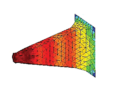
 Since the concepts covered in the previous two paragraphs are tough to grasp in words, we’ve included images that clearly show them. Figures 1 and 2 provide computer simulations of two different types of horn flare that show how the sound wave changes curvature as it moves through the horn. They also show how the sound wave front intersects the wall boundary in a perpendicular manner. The horn in Figure 1 is a variant of the hyperbolic-exponential horn, or hypex horn. It was specially calculated to provide a very smooth rounding of the wavefront as it travels through the horn to the mouth. This horn does not exhibit uniform directional control, but instead gets progressively narrower at higher frequencies.
The Mouth
 The horn in Figure 2 is a conical horn that stops abruptly at the mouth. This was done to highlight some of the effects that happen at the horn’s mouth. Near the mouth, the sound can be seen to sharply bend around the corner of the horn, and the surface of the wave is no longer a smooth arc.
The physics of waves, including sound waves, dictates that they bend around objects. This behavior is known as diffraction, and is most prominently seen when the wavelength is close to the same size as the object. You can illustrate this for yourself by taking a horn, turning it away from you, and listening to it from behind. Frequencies will still be clearly audible behind the horn, as they have bent around the horn mouth.
Further, as sound travels through the horn, a portion of the energy from the sound wave does not emerge from the mouth, but is instead returned back down towards the throat. This effect is most pronounced at the abrupt flare termination of the horn mouth. To understand this behavior in a more intuitive sense, it is useful to consider an analogous circumstance from the world of optics.
When you stand in front a pane glass window, you can see through the window, but you can also see a faint a reflection of yourself back in the glass. The back reflection in the glass results from the fact that glass and air do not have the same index of refraction. When light transitions between different physical mediums (i.e., glass and air), the mismatch in index of refraction causes the reflection.
In acoustics, there is a quantity analogous to index of refraction known as the acoustic impedance. The acoustic impedance is defined as [Pressure ÷ Volume Velocity]. We’ve already established that the relationship between pressure and volume velocity changes as sound moves through the horn. Another way of saying this is that the acoustic impedance is changing through the horn.
This change in acoustic impedance is most drastic at the horn mouth, where the horn’s controlled expansion stops and free space begins. This sharp change results in the most pronounced reflection back into the horn. This reflected energy then travels back through the horn and re-emerges later in time.
The world would be much simpler if horns were infinitely long, and we never had to worry about the mouth effects of diffraction and reflection. In the real world, mouth effects have substantial influence on the performance of professional audio horns. We will revisit these mouth behaviors in another FRONT of HOUSE article.
More To Come
By now it should be clear that horns are a very deep topic. We’ve introduced several new concepts and equations, and yet presented an entire article without getting into the specifics of horns in professional audio! In future installments we will further discuss horns on topics including horn evolution, directional control, and performance as part of professional loudspeaker systems.
Computer simulations of sound waves in horns courtesy of John Sheerin of JHS Audio (jhsaudio.com).
Phil Graham is the senior engineering consultant of Passband, llc (www.passbandllc.com).