Other than dead silence, feedback must be the most hated thing in professional audio. Those little blasts, often at higher frequencies where the ear is very sensitive, disrupt the performance and draw attention to the technology behind it. Feedback has been with us since the speaker first met the microphone, and is something every practitioner of the art has had to face. As long as loudspeakers are returning sound information back to presenters and performers, the potential for feedback will remain. In this article we’ll unpack this pesky beast that forcefully inserts itself into monitor wedges and lapel microphones. We dive into how a monitor loudspeaker’s response can change based on the listening location and how these response changes influence monitor wedge performance.
Feedback Defined
Feedback has come to mean several things in modern life. You can ask for feedback on a presentation, set the feedback percentage for delay effects, use “negative feedback” in an electronic circuit, or anger the singer with a squealing monitor wedge. In all definitions of feedback, the core concept hinges on the return of information, electrical signals, or sound back to the original source after a period of time. For a delay effect, the feedback may arrive many tens or hundreds of milliseconds (ms) after the initial signal. By contrast, feedback in an electronic circuit (such as an amplifier) is returned back to the source nearly instantaneously. Sound returning back to the singer’s microphone from the monitor lies somewhere in between, usually taking a few milliseconds due to the acoustic path-length between transducers.
Feedback is the return of electronic signals or sound after a period of delay and the subsequent combination of the returned signal with the original. The three key parameters that define the nature of the interaction between the original and returned signal are the phase shift, polarity and gain relative to the original signal. Feedback at a specific frequency will occur if three things happen:
• First, the frequency must be in phase,
or nearly in phase, at the point where
the original signal and returned signal
meet. If the return signal is out of
phase with the initial input, it will
cause cancellation, not reinforcement,
and feedback will not occur.
• Second, the polarity of the two signal must
be the same. If two signals arrive in phase,
but the polarity of one is positive (+) and
the other negative (-), they will cancel.
• Third, the amplitude of the frequency must
increase with every trip around the
feedback “loop.” Another way of saying this
is that the gain for a feedback frequency,
as it makes the trip from wedge to
microphone over and over, must remain
greater than one.
As an example, if the gain of a loop is 1.5, the feedback signal will be 1.5 times the original on the first trip around the loop and 1.5 x1.5 = 2.25 times on the second trip around the loop. On the tenth trip around the loop, the gain is almost 58 times the original signal! This explains why a feedback frequency can get very loud very quickly.
Let’s compare what happens in an electronic circuit with what occurs in a monitor wedge to understand further how these three concepts (phase, polarity, and gain) work together in defining feedback. For electronic circuits, the phase shift is very small for all audio frequencies because the delay around the loop is essentially zero. Oftentimes the gain of the electronic feedback signal is substantial. The reason one can send a “hot” signal back into the original circuit is that the electrical polarity is negative, or inverted, relative to the original signal. The inverted polarity signal fed back into the circuit acts to correct distortion and improve the circuit behavior.
By contrast, the time it takes sound to travel in the air between the monitor wedge and the microphone causes a propagation delay of a few milliseconds, an eon in electronic circuit terms but very short in human terms. This delay introduces phase shift, and that phase shift is different for every frequency. For a given delay, low frequencies, with their long wavelengths, experience low phase shift. High frequencies, with their shorter wavelengths, experience more phase shift.
Due to the delay from monitor to microphone, all frequencies arrive at the microphone with different relative phases. Some frequencies will end up completely in phase, some will be completely out of phase, and some will be in between. Changing the polarity from positive to negative will only cause a swap of which frequencies are in phase and which frequencies are out of phase. This means a polarity swap will reduce some feedback frequencies at the expense of causing other ones. Polarity swap between adjacent wedges is sometime effective for mitigating low frequency feedback when there are multiple open microphones.
A monitor wedge and microphone combination has a comparatively low gain, meaning the (typically) cardioid microphone doesn’t pick up as much of the monitor’s volume. This means the gain between the monitor and microphone is usually well below one. As noted, the point where feedback begins is where the gain between wedge and microphone increases over one.
Shortly before a wedge “takes off” into full blown feedback, you will often hear a hollow “ringing” sound. The ringing from a monitor that occurs just before feedback happens as the gain between monitor and microphone creeps upwards towards unity. The closer the gain is to unity, the greater number of repeats between the wedge and microphone required for the frequency to die out. As an example, if the gain is 0.95, after 15 round trips the gain is only reduced to 0.46; it takes 45 cycles between microphone and monitor to reduce the gain to 0.1! If a monitor is consistently exhibiting the ringing immediately before feedback, a slight change in the performer’s location, a music stand, air temperature or humidity might be enough to send the wedge squealing.
Driver Effects on Coverage Pattern
Now that the conditions for feedback are clearer, we can discuss how the design of monitor loudspeakers influences the likelihood of feedback. We already mentioned that swapping monitor (or microphone) polarity has little overall effect, merely trading one set of feedback frequencies for another. Similarly, while we have some control over the gain through microphone choice and placement, eventually the wedge will be turned up sufficiently to feed back.
This leaves us with phase shift effects from the loudspeaker’s design to influence how feedback-proof a monitor will be. More specifically, the differences in phase shift that result from the drivers’ directional behavior and the physical spacing distance between the low and high frequency loudspeaker transducers.
At low and mid frequencies, the wavelengths of sound are several feet long, much bigger than the driver diameter. As the frequencies get higher, the driver’s dimensions become comparable to the wavelength of sound being reproduced. At 1200Hz, the wavelength is about one foot, or approximately a driver diameter for a typical 12-inch floor monitor woofer. At this frequency, the driver’s coverage angle begins to narrow. As frequencies get higher, the driver grows progressively more directional.
The driver becomes more directional because of phase shift, specifically the phase difference between sound that comes from different points on the speaker cone. Imagine standing off to the left of the monitor woofer and listening. Sounds from the left side of the speaker cone will arrive at you sooner than sounds from the right side of the speaker cone. This is because you are farther from the right side of the speaker cone than the left side. At low and mid frequencies, this difference in distance is of little effect. The wavelengths are long compared to the cone diameter, and therefore the phase difference is minimal. However, when the wavelengths become shorter, comparable to the dimensions of the cone, the phase shift between different points on the cone becomes greater. The radiation of the left and right side of the cone is now less in phase, and the result is that the woofer’s coverage angle starts to narrow.
The directional response of a typical compression driver and horn is even more complicated at 1200Hz, and indeed would serve as a good topic for a future article here in FOH. Generally, horns have less pattern control at 1200Hz than at higher frequencies. Unfortunately, the way the directional control changes between 5000 and 1200 Hz is complicated, and will be somewhat different for various high frequency horn designs.
Adding the Crossover
The crossover frequency between the woofer and the horn also happens to be about 1200Hz. The loudspeaker designer therefore has to combine a woofer with narrowing coverage and a horn with widening coverage in a way that provides the smoothest possible coverage through the crossover point, the region where both drivers equally bear the burden of reproducing sound. This is a complicated task, full of pitfalls and compromises.
Even if the loudspeaker designer is very skilled, and mates the drivers with differing coverage patterns in the best possible way, there remains the matter that the drivers are still separated a physical distance at the crossover point. As you move the microphone in the vicinity of the loudspeaker wedge, you change the relative distance from each driver, and therefore the relative phase shift relationship between the drivers. In some locations, the drivers will be more in phase, and in other locations they will be more out of phase, all depending on the relative distances between the two drivers and the microphone.
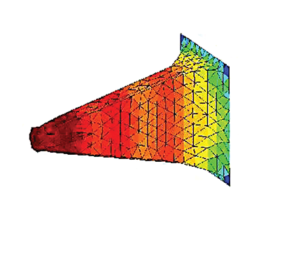
These phase shift effects are best illustrated graphically. The response differences due to driver spacing can be seen in figures 1, 2 and 3. Each figure represents a two-way loudspeaker with the horn mounted next to the woofer. There are four plots in each figure:
• The upper left plot is the frequency
response of the individual drivers
• The lower left plot is the horizontal
coverage pattern of the speaker viewed
from above.
• The lower right plot is a 3D projection of
the horizontal response coverage
• The upper right plot views the horizontal
coverage pattern on end
Figure 1 represents the directional response of a Linkwitz-Riley fourth-order filter (LR4) with perfect point source drivers. Figure 1 is the idealized case for directional response between two separated drivers. Notice that the coverage is by no means uniform everywhere. There are substantial dips at specific listen angles, but the maximum response is on axis. Because our sources are physically spaced apart, this is the best our speaker coverage pattern can look.
 Figure 2, by contrast, shows the same LR4 filter with real drivers. The net result is awful. There is now a giant hole in the response almost directly on axis! Textbook crossover filters, when coupled to real-world drivers, can often produce unsatisfactory results.
 Figure 3 shows the response of the real world drivers using carefully designed crossover filters. The end result is similar to Figure 1, but the crossover filters bear no resemblance to the simple LR4 case used in Figures 1 and 2. One filter is second order, the other is third order, and overall, it is a much more complicated electrical system. The end result requires substantial loudspeaker design knowledge and measurement to achieve. Even so, we have not eliminated the location-dependent phase shift effects, but merely minimized them as much as feasible.
Takeaways
We have systematically defined feedback and discussed the factors that cause its occurrence. We then discussed how loudspeakers have changing coverage directly in the frequency region where crossover points are common. Finally, we showed how the combination of loudspeakers and different crossover filters can produce dramatically varied response results based on listening position.
Considering what’s depicted in figures 1, 2 and 3, one might wonder, “Why not exclusively utilize coaxial monitor loudspeakers? Since coaxials place both drivers as physically close together as possible, that solves all our problems, correct?” Unfortunately, the benefits of using coaxial transducers are not so clear-cut. Coaxial designs can have more limited power handling, rougher frequency response, and overly narrow coverage at certain frequencies. While certain aspects of coaxes are advantageous for floor monitors, they are no monitor panacea.
Monitor engineering is a messy business. The monitor mixer is responsible for many different mixes, battling feedback, communicating with performers and presenters, and generally juggling chain saws. It is tempting to utilize loudspeakers of questionable pedigree for monitor duty, when in reality monitors should probably be the most carefully-designed loudspeakers in a production company’s inventory. Low stress, feedback-free shows will quickly justify the additional expense of high-quality monitor wedges.
Figures were generated by Charlie Hughes in MATLAB. Charlie’s website is at www.excelsior-audio.com.
Phil Graham is the principal of PASSBAND, llc (www.passbandllc.com). He started building loudspeakers more than 15 years ago. Email him at [email protected].