Audio engineers hear and see the term “impedance” almost daily, whether it’s regarding the output of a microphone, the input to a mixing console, or in the specifications for a loudspeaker. Let’s see if we can take some of the mystery out of the subject.
Impedance Is the Same Thing as Resistance… Sometimes
Resistance and impedance are both opposition to the flow of electricity and are measured in Ohms (Ω). The symbol for resistance is R, while the symbol for impedance is Z. When a circuit has a higher resistance, more voltage is required to push a given amount of current through it. If you’re rusty, revisit Ohms law, which states:
V = I x R
where V = voltage, I = current, and R = resistance.
Here’s the catch: resistance is opposition to the flow of electricity in a DC (Direct Current) circuit, but audio is AC (Alternating Current), and audio circuits are reactive — they contain components that store and release energy such as capacitors and inductors which react with each other as frequency varies — and frequency is always changing in music. This reactance, combined with resistance of components such as um, resistors, gives us impedance. You can use Ohm’s law for AC circuits but instead of using R, use Z.
Input Impedance Versus Output Impedance
The impedance of an output (also called source impedance) measures how easily power can flow from that output. Input impedance measures an input’s opposition to the flow of power from an output and gives you an idea of how much power the input device will “pull” from the source in order to get work done. Input impedance is also known as “load impedance,” a load being a device in a circuit that consumes electricity while doing its job (a loudspeaker, for example).
If we set the clock back to Ye Olden Days of audio, we’d find out that it was important to match impedance between devices: the output impedance of the sending device should be the same as the input impedance of the load. Like a lot of audio fundamentals, this concept came from the phone company because they were trying to ensure maximum power transfer of audio across long-distance telephone circuits which, were tube-based at the time.
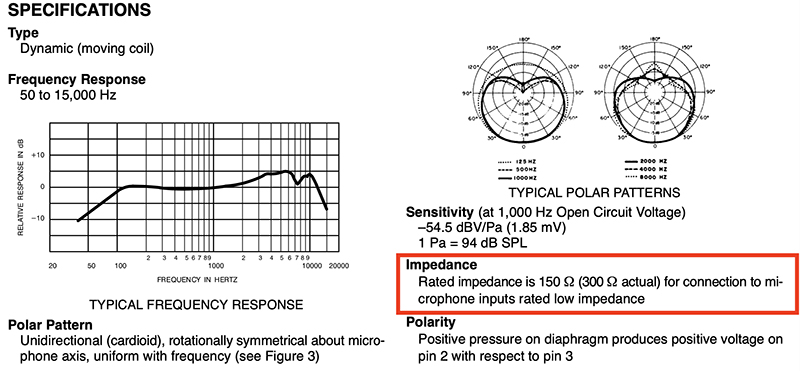
And then came the transistor, an inexpensive, efficient amplification device that could maximize voltage transfer as opposed to power transfer — a trait which is really helpful for low-level audio signals such as microphone, line and instrument signals. When it comes to low-level signals, we’re not concerned with transferring a lot of power. We simply need to get the signal (the voltage) from one device to another with minimal loss. The general rule for maximum voltage transfer is that the load impedance should be at least ten times that of the source impedance. When you see a microphone with an output impedance of 200Ω (which is typical), that microphone should be happy when connected to an input with an impedance of 2kΩ or higher. In this case, “happy” means that the microphone’s frequency response and noise level are maintained as the manufacturer intended. (See Fig. 1)
There are microphones with high impedance outputs (appx 10kΩ), but try to avoid them because they are prone to interference as well as HF rolloff when cable length increases beyond around 20 feet. Hi-Z mics typically have screw-in connectors and cables terminating in a ¼-inch TS plugs, so they should be easy to spot (and avoid).
A Match Made in Hell
What happens with modern audio gear when we have an impedance mismatch? Let’s suppose you make a TS to XLR cable and use it to connect the output from an electric bass directly to the microphone input on a mixing console. The pickup in a passive bass has an output impedance somewhere in the vicinity of 10kΩ, so it wants to terminate (connect to) an input with an impedance of 1MΩ or higher. Microphone inputs on pro audio gear usually don’t have load impedances that high, they generally run more like 1.5kΩ to 5kΩ. You won’t harm anything by connecting a bass to a mic input, but you can expect a loss of high end due to the impedance mismatch.
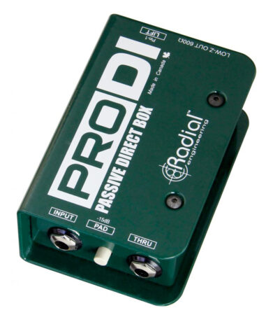
The other problems with connecting a Hi-Z instrument to a Low-Z input include a loss of signal level and the possibility that the output from the instrument might overload the microphone input, causing distortion. The solution to all these issues is the direct box, which provides a “Hi-Z” input that makes the instrument pickups happy, and a low impedance output which makes the microphone preamp happy. Some DIs use a transformer to perform this miracle while others use solid-state devices like a transistor (J-FET, in particular). (See Fig. 2)
Due to the high impedance pickups, electric guitars and basses are particularly sensitive to cable length. Cables add capacitance which can roll off the high end, so keep instrument cables shorter than 20 feet.
Banana Split
What if you need to split the signal from say, the output of a mixing console? You can do so using modern gear under most circumstances, if the load impedance is significantly lower than the source impedance of the output. But don’t do the opposite and try to “Y” two sources into a single input. This is likely to create audible problems and could damage the gear.
Power Amplifiers and Loudspeakers
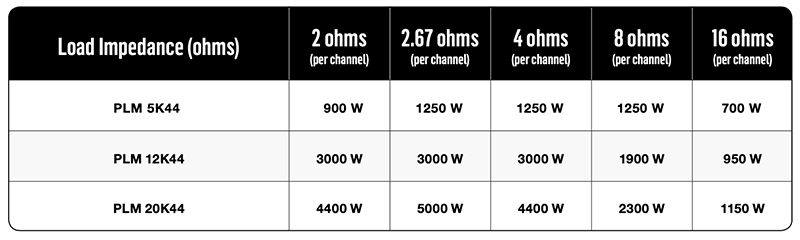
When considering what power amp to use with passive speakers, we are concerned with maximum power transfer, and that’s why it’s smart to match the output impedance of the amp to the input impedance of the loudspeaker (this is particularly important when dealing with tube guitar or bass amps). If the speakers are rated at 4Ω, and the amp is rated for 100 watts per channel into a 4Ω load, then you can be confident that the amp will deliver its rated power. If, however, you connect an 8Ω load to that amplifier, the amp will probably deliver only one-half of its rated output. (See Fig. 3)
On the other side of that equation, if you connect a 2Ω load to the amplifier you may be putting too much demand on the amp, which could result in overheating or a shut-down. One of the big advantages of using powered speakers is that the manufacturer has already worked this out, and you can be confident that the internal amplification is matched to the drivers.
Steve “Woody” La Cerra is the tour manager and FOH engineer for Blue Öyster Cult, and Jon Anderson & The Band Geeks. He can be reached via email at [email protected].