Last month, we introduced some of the principles behind the horn waveguides that are ubiquitous in professional audio. In this follow-up, we’ll discuss the directional nature of horns, building on the prior discussion about how horns operate and how sound waves travel through them.
Previously, we explained that horns perform acoustic and directional functions and introduced the quantities of pressure, volume velocity and sound intensity. We showed horns to be tubes that transition from one cross-sectional area to a different cross-sectional area. Specifically, horns are designed in such a way that a high pressure near the loudspeaker driver is converted to a high volume velocity near the horn’s exit.
We then discussed how sound moved through a horn from the compression driver into open air. We defined the horn throat, flare and mouth. We discussed reflections in a horn, including the strongest one at the mouth. If you missed that August 2012 article, we suggest you revisit it in print or online at fohonline.com.
This month, let’s look at directional control of sound with horns, including a history of its pursuit, the general form of today’s “constant directivity” horns, and the principles of operation behind the CD approach.
Background
For modern professional loudspeaker horns, directional control is arguably the most important behavior and feature. From small ceiling loudspeakers to line array waveguides in large concert systems, loudspeaker designers are looking to influence where sound travels in space. The core idea of directional control, or directivity, is that we can change the loudness of sound based on the direction it propagates relative to the horn flare’s physical location. Generally, the desired result is that angles in front of the horn will receive broadband sound of high loudness, while those off to the sides and back of the horn will experience greatly reduced sound levels.
There have been numerous approaches towards this goal, with varying degrees of success. In the dawn of sound reinforcement, the central goal was improving the evenness of sound distribution over a desired coverage angle, as these early horns did not provide even coverage. Specifically, the angle of the audience that received similar volume midrange sound was much wider than the area of the audience that received similar volumes of high frequencies. Horn designers wanted to improve on this disparity, so the included coverage angles of midrange and high frequencies were similar.
 Coverage Improvement Attempts
Early improvements in directional uniformity came in several basic forms. One of these forms is the radial horn (Fig. 1). The classic radial horn was a dual-profile horn flare. The flare profile (typically conical) in one plane provided more even sound coverage, while the flare profile (typically exponential) in the other plane helped provide good acoustic loading for the compression driver. As shown in Fig. 2, the directional response in one plane was somewhat even, but the coverage angle still narrowed rapidly in the other plane. This was still a substantial improvement on the purely exponential horns that had been used previously.
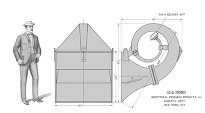
.") A second form used to improve directional evenness was the multicell, or sectoral, horn (Fig. 3). The sectoral horn was an array of flares (typically exponential) that, collectively, provided more even directivity than a single exponential flare (Fig. 4). As the coverage of an individual exponential horn is very narrow at high frequencies, an array of them can increase the angle of high frequency coverage.
A second form used to improve directional evenness was the multicell, or sectoral, horn (Fig. 3). The sectoral horn was an array of flares (typically exponential) that, collectively, provided more even directivity than a single exponential flare (Fig. 4). As the coverage of an individual exponential horn is very narrow at high frequencies, an array of them can increase the angle of high frequency coverage.
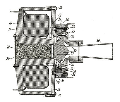
 Developed to improve directional evenness, a third form was the acoustic lens (Fig. 5). The acoustic lens is not a horn flare, but rather a device that modified the path lengths of sound to broaden the sound coverage. As sound exits the lens at different points, the varying path lengths through the lens introduce different delay times that shape the sound’s directional coverage. The acoustic lens can be seen as the historical father of the modern line array waveguide.
 The Constant Directivity Horn
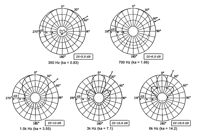
Radial horns, sectoral horns and acoustic lenses each had their own collection of undesirable compromises. Seeking to reduce these compromises, Don B. Keele of Electro-Voice published a seminal AES paper in 1975 entitled “What’s So Sacred About Exponential Horns?” In this paper, he enumerates what is now broadly known as the constant directivity horn (Fig. 6). Keele demonstrated the general effectiveness of this horn configuration with directional plots for multiple different coverage angles (Fig. 7).
 The CD horn flare has three distinctive regions, each with a specific purpose. At the throat, adjacent to the compression driver, is an exponential flare designed to provide acoustic loading. Moving outwards from the exponential throat section is a section with conical flare (i.e., straight side walls). This section provides the constant directivity characteristic of the horn’s angular coverage. A third region near the horn mouth is a secondary expansion designed to reduce narrowing of the coverage caused by the abrupt termination of the horn mouth.
 Keele’s work made a substantial lasting impact on the industry. He largely conquered the problem of consistent, broadband directional coverage that had been sought by loudspeaker designers for almost 50 years. Most modern professional loudspeaker waveguides have their heritage in Keele’s constant directivity work.
Constant Directivity – Operating Principle
At the core of the CD horn behavior is the conical flare section with straight side walls. This section of the flare sets the coverage angle by providing a constant direction of propagation for the sound wave at the horn wall, due to the wall being straight. The majority of the frequency spectrum leaves the horn flare and travels into free space in the conical area of the horn, where the exit angle is constant. The throat’s buildup to the conical section, and the secondary flare at the mouth, both serve the purpose of minimizing secondary horn behaviors from polluting constant directivity. In other words, carefully shaping the throat and mouth allows the middle of the horn to properly perform its task of consistent directionality.
Physics dictates that acoustic waves bend fairly easily around objects whose dimensions are comparable to, or smaller than, the wavelength. Known as diffraction, this behavior is easily illustrated by taking a loudspeaker, turning it so the drivers face away from you, and listening to it from behind. Some frequencies will still be clearly audible behind the box, as they have bent around the loudspeaker enclosure.
As frequencies get lower, wavelengths are longer and a horn’s ability to provide directional control decreases. Sound bends around the edges of the horn and spills around the loudspeaker. It would be intuitive to think that this causes the directional coverage of the horn to widen due to diffraction. However, in reality, there is a range of frequencies where the coverage pattern narrows due to diffraction. This is due to the physics of diffraction, and it leaves a frequency range with narrower dispersion of sound. The secondary expansion of the horn near the mouth, after the conical flare, specifically helps reduce this diffraction effect and keep the directivity more constant in the horn’s lower registers, where mouth effects are important.
Conclusion
The constant directivity horn, in all its variants, is a cornerstone of professional audio. It allows those working in professional audio to more evenly aim and distribute sound across the audience area. It also opened up the industry to the concept that sound distribution is controllable, and that designers can provide even — or intentionally skewed — coverage for the benefit of the loudspeaker, array and audience.
The third part of this series on horns will investigate current horns in professional audio, including line array waveguides, the current state of constant directivity horns, techniques for improving horn performance and areas of ongoing study in horn behavior.
The author would like to thank Don Keele for his assistance on this article. His 1975 preprint on constant directivity horns is available for purchase at aes.org/e-lib/browse.cfm?elib=2394.
Phil Graham is the senior engineering consultant of Passband, llc (passbandllc.com). Email him at [email protected].